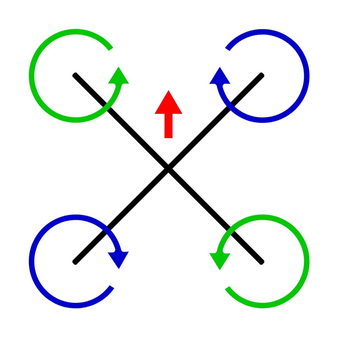

You get a longer body which is good for space and you get the more optimal arm placement of the X frame. This is frame type takes the best of the H and X frames and joins them together. Hybrid X: The title does not really describe it too well. The angle of the arms means that the body can be smaller as it does not need the length to separate the arms. This provides the most balanced performance as each motor operates equally. The Distance between all the motors is equal. True X: As the name suggests, this is where the frame is shaped exactly like an X. While you may find some of these frames around, they are much less common due to the fact they are quite bulky and the motor position is less optional for good moment of inertia (due to the long arms). This normally leads to a longer body section to avoid the blades touching. The Arms stick out directly from the body. H: This is where the frame looks like an H on its side. The frame also takes it a step further with an optimised design to save weight, a single-piece top plate for added strength and rigidity, a thicker bottom plate for more durability, and lower stand-offs for improved CG and better handling. By going with a "slammed-deck" design, the weight of the frame stays the same, but the durability and flight handling are further improved. The JB edition increases durability by going to a single-piece top plate and changing the bottom plate from 2mm to 3mm. JB comes with a lot of experience in the realm of quadcopters, and it is this vast knowledge that has helped Lumenier create a masterpiece. Building on the success of the popular QAV-S frame, Lumenier has partnered with JB to take things a notch higher. Three no-fly zones were defined for each of the auxiliary power generators, so in case there is a failure in the quadcopter, it does not cause any damage to the campus infrastructure.Features like an arm locking mechanism with the help of press nuts, a split bottom plate that gives enough room for a micro camera, and the isolated 20x20mm and 30x30mm stack mounting in the centre and the rear lets pilots take care of their electronic stacks make this frame stand out. The default data contains poses for specific locations at which the toy quadcopter uses its cameras so the pilot on the ground can estimate the height of the snow on the roof. To clear the values in the waypoint and no-fly zone panel, click Clear. To load the default trajectory, press the Load Default button. To load the last saved trajectory, click Load. This button only saves your last trajectory. To save the trajectory that is currently in your panel, click the Save button.

To generate the trajectory, add the waypoint and no-fly zone characteristics to the respective panels, then click Generate Trajectory. This panel plots the trajectory over the Apple Hill campus aerial schematic based on the waypoints and no-fly zone characteristics. Use the Add, Delete, Edit, OK, and Cancel buttons in the same way as for the Waypoints panel. You can visualize the variables for the quadcopter in one of the following ways:
#Quadcopter geometry x how to
For more information on how to do this, see the Simulink Control Design Get Started with Simulink Control Design (Simulink Control Design)). To make sure that the trajectory generation tool works properly, the example implements a test in the trajectoryTest file. The model uses the trimLinearizeOpPoint to linearize the nonlinear model of the quadcopter using Simulink Control Design (R).

To include these models, you can change the VSS_ENVIRONMENT variable in the workspace to toggle between variable and fixed environment models. The models implement several Aerospace Blockset™ environment blocks, including those for atmosphere and gravity models. To include sensor dynamics with these measurements, you can change the VSS_SENSORS variable in the workspace. The example stores the characteristics for the sensors in the file sensorVars. An Inertial Measurement Unit (IMU) to measure the angular rates and translational accelerations.


 0 kommentar(er)
